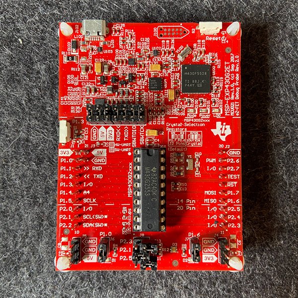
This was a small project implementing two PIR motion sensor modules to track a user within two zones. This was created to experiment with a Texas Instruments MSP430 Microcontroller and the C language. The focus for this project was software, including how to implement interrupts and other firmware level best practices.
This project was inspired by knowledge gained in a Microprocessors course.
Motion Tracking Fan
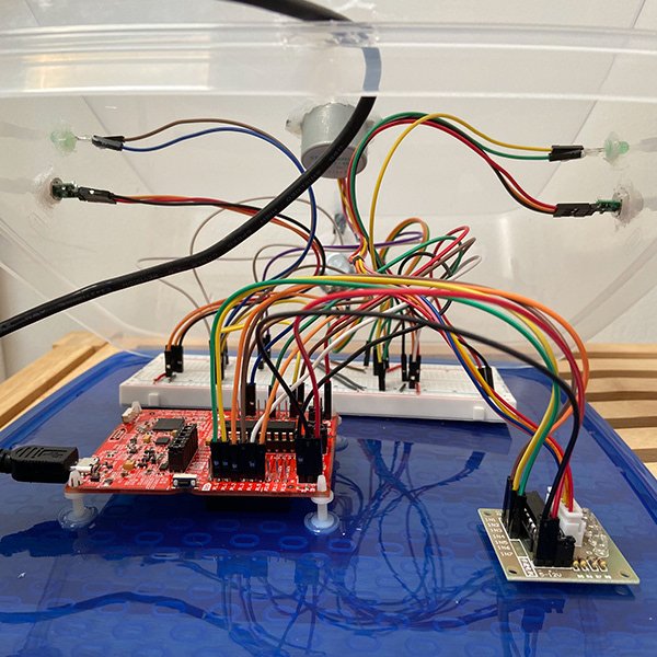
Here one can see an image of the completed Motion Tracking Fan in order to get a better idea as to what this project consists of.
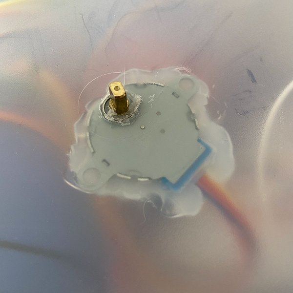
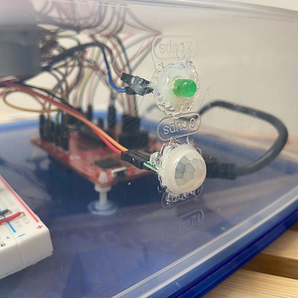
A single pre-made fan rests upon a platform rotated by a stepper motor. This stepper motor is controlled by the MSP430 within that is receiving input from the PIR motion sensors.
When a user walks from one PIR zone to another the fan will follow. This is seen clearly in the next diagram below.
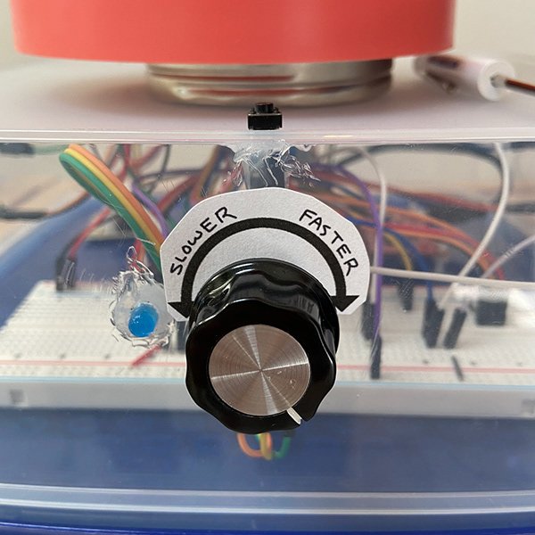
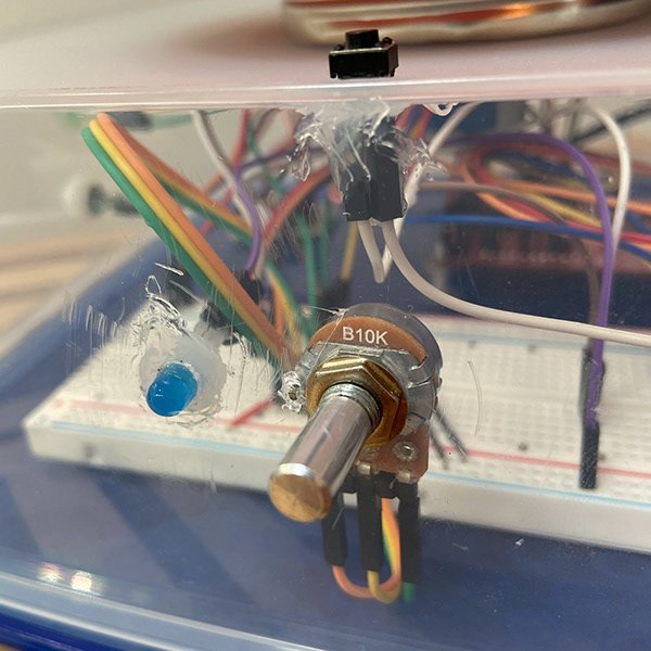
The Potentiometer allows a user to variably adjust the speed at which the fan will track a user, and is activated via the button above it.

This diagram better illustrates the operational range of the PIR sensors, and the orientation of the hardware components.
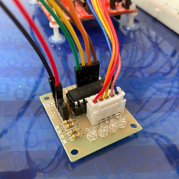
This wiring schematic, created using Fritzing, illustrates the connections between the MSP430 and the peripherals.
As this project focuses mainly on software design and is a proof-of-concept, this wiring schematic was not converted into a PCB and packaging was not considered. For a more complete project and associated PCB design, see my Facial Recognition Door Lock project.

In addition, a handout of this project was created for a K-12 grade setting. A higher quality image can be viewed in the associated GitHub repository.